
7 Segment Display using Shift Register and Arduino
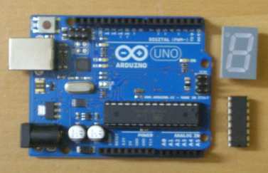
Its easy to control 7 segment display if each segment is hooked up to its own pin on the arduino, 7 pins will be used up for 1 display. But using so many pins doesn't seem sensible. Using Shift Register this can be brought down to 3 pins.
I had only one shift register available so I made a simple seconds keeper. I need atleast one more shift register to make a stopwatch which is what I initially wanted to make.

There are enough videos for 7 segment display on Youtube that I won't bother putting up another for something so trivial.
Edit: Added Code on 29th July 2012
//Define which pins will be used for the Shift Register control
int dataPin = 2;
int latchPin = 3;
int clockPin = 4;

//The byte sequence
int seq[14] = {0x3F,0x06,0x5B,0x4F,0x66,0x6D,0x7D,0x07,0x7F,0x6F};

void setup()
{
	//Configure each IO Pin
    pinMode(dataPin, OUTPUT);
    pinMode(latchPin, OUTPUT);
    pinMode(clockPin, OUTPUT);
}

void loop()
{
    for (int n = 0; n < 10; n++)
    {
    	//Pull latch LOW to start sending data
        digitalWrite(latchPin, LOW);

        //Send the data
        shiftOut(dataPin, clockPin, MSBFIRST, seq[n]);

        //Pull latch HIGH to stop sending data
        digitalWrite(latchPin, HIGH);

        delay(1000);
    }
}